
KSWC typeUniversal Coupling
Hollow cross-shaft universal coupling
Universal Coupling
KSWC-type hollow cross-shaft universal coupling adopts a hollow shaft structure design, suitable for heavy industrial transmission applications such as metallurgy rolling mills, featuring high torque, high reliability, and easy maintenance. The product is manufactured strictly in accordance with the NBR 8008 (ISO 1940) standard to ensure dynamic balancing accuracy.
Rated torque56 ~ 1000 kN·m
Flange diameter225 ~ 550 mm
Axial deflection angle8° / 15°
Total length1415 ~ 2625 mm
Weight range198 ~ 2495 kg
Standard specifications9 models
Product Features
- Hollow shaft design, reduced weight
- Rated torque 56 ~ 1000 kN·m
- Axial deflection angle β = 8°/15°
- Flange diameter 225 ~ 550 mm
- Compliant with ISO 1940 dynamic balancing standard
- High-strength alloy steel forging
Applications
- Hot rolling mill drive system
- Cold rolling mill main drive
- Large press drive
- Mine hoist
- Heavy-duty crushing equipment
以下为 KSWC型 的工程结构图,包含主要尺寸标注及端面视图。
结构形式
从动端
n=8
n=10
n=16
主动端
N=8
N=10
N=14
表4:KSWC型十字轴式万向联轴器基本参数和主要尺寸
| 数值 / 型号 项目 | KSWC 225 | KSWC 250 | KSWC 285 | KSWC 315 | KSWC 350 | KSWC 390 | KSWC 440 | KSWC 490 | KSWC 550 |
| 基本长度 L (mm) | 945 | 1025 | 1145 | 1260 | 1469 | 1575 | 1760 | 1860 | 2055 |
| 总长度 Lt (mm) | 1415 | 1475 | 1670 | 1765 | 1999 | 2070 | 2215 | 2375 | 2625 |
| 伸长量 La (mm) | 650 | 650 | 750 | 750 | 800 | 800 | 800 | 900 | 1000 |
| 公称扭矩 Tn (kN·m) | 56 | 80 | 120 | 160 | 225 | 320 | 500 | 700 | 1000 |
| 疲劳扭矩 Tf (kN·m) | 28 | 40 | 58 | 80 | 110 | 160 | 250 | 350 | 725 |
| 轴线折角 β (°) | 8/15 | 8/15 | 8/15 | 8/15 | 8/15 | 8/15 | 8/15 | 8/15 | 8/15 |
| 法兰直径 Df (mm) | 225 | 250 | 285 | 315 | 350 | 390 | 440 | 490 | 550 |
| 回转直径 D (mm) | 225 | 250 | 285 | 315 | 350 | 390 | 440 | 490 | 550 |
| D1 (js11) (mm) | 196 | 218 | 245 | 280 | 310 | 345 | 390 | 435 | 492 |
| D2 (H7) (mm) | 135 | 150 | 170 | 185 | 210 | 235 | 255 | 275 | 320 |
| D3 (mm) | 135 | 155 | 175 | 200 | 225 | 245 | 280 | 305 | 345 |
| Lm (mm) | 125 | 140 | 160 | 180 | 195 | 215 | 260 | 270 | 305 |
| K (mm) | 20 | 25 | 27 | 32 | 35 | 40 | 42 | 47 | 50 |
| t (mm) | 5 | 6 | 7 | 8 | 8 | 8 | 10 | 12 | 12 |
| b (mm) | 32 | 40 | 40 | 40 | 50 | 70 | 80 | 90 | 100 |
| g (mm) | 9 | 12.5 | 15 | 15 | 16 | 18 | 20 | 22.5 | 22.5 |
| nxd (mm) | 8×17 | 8×19 | 8×21 | 10×23 | 10×23 | 10×25 | 16×28 | 16×31 | 16×31 |
| 法兰直径 Df' (mm) | 315 | 330 | 390 | 435 | 480 | 520 | 600 | 650 | 710 |
| 回转直径 D' (mm) | 315 | 330 | 390 | 435 | 480 | 520 | 600 | 650 | 710 |
| D1' (js11) (mm) | 285 | 300 | 355 | 390 | 430 | 480 | 550 | 595 | 650 |
| D2' (H7) (mm) | 220 | 210 | 260 | 275 | 320 | 360 | 420 | 450 | 520 |
| Lm' (mm) | 140 | 155 | 175 | 190 | 210 | 235 | 265 | 290 | 325 |
| K' (mm) | 30 | 30 | 35 | 35 | 40 | 50 | 55 | 55 | 60 |
| t' (mm) | 5 | 6 | 7 | 8 | 8 | 12 | 12 | 12 | 15 |
| Lg (mm) | 420 | 450 | 505 | 575 | 640 | 685 | 755 | 800 | 880 |
| Nxd (mm) | 8×19 | 8X21 | 8X21 | 10X23 | 10X23 | 10X25 | 10X28 | 14X31 | 14X31 |
| Do (mxz) (mm) | 3×34 | 3×38 | 3×42 | 3×50 | 5×34 | 5×36 | 5×42 | 5×44 | 5×50 |
| 法兰螺柱 规格 | M16 | M18 | M20 | M22 | M22 | M24 | M27 | M30 | M30 |
| 法兰螺柱 拧紧力矩 (kN·m) | 0.2 | 0.28 | 0.39 | 0.53 | 0.53 | 0.69 | 1.01 | 1.4 | 1.4 |
| 转动惯量 (kg·m²) | 1.165 | 1.77 | 3.639 | 6.318 | 10.08 | 16.79 | 32.76 | 51.85 | 88.74 |
| 质量 (kg) | 198 | 272 | 409 | 553 | 772 | 973 | 1378 | 1732 | 2495 |
注:以上尺寸均为参考值,实际尺寸以工程图纸为准。如需其他规格,请联系我们定制。
-
Determine operating conditions
Clarify transmitted torque, speed, working environment, and installation space
-
Calculate load
Determine the calculated torque Tc = K·Tn based on the characteristics of the prime mover and driven machine
-
Select series
Select the appropriate series based on the connection type (flange/spline) and telescopic length
-
Confirm specifications
Refer to the parameter table and select the smallest model that satisfies Tc ≤ Tn
-
Check dynamic balancing
Verify according to ISO 1940 G6.3 grade; for high speeds, upgrade to G2.5
Notes
- During installation, ensure the alignment error between the two shafts is within the allowable range.
- Regularly check the lubrication status of the cross shaft bearings.
- The working angle must not exceed the rated deflection angle.
- In high-temperature environments, please use high-temperature resistant grease.
Common Applications
Hot strip rolling millHigh temperature, heavy impact225~1000 kN·m
Cold rolling finishing lineHigh precision56~320 kN·m
Wire rod rolling millHigh-speed continuous rolling56~500 kN·m
Heavy-duty pressImpact load320~1000 kN·m
Large mining millLow speed, high torque500~1000 kN·m
You May Also Like
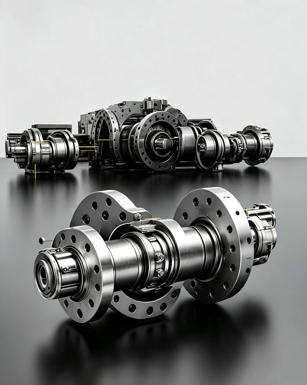
SWC type
Integral fork curved tooth universal coupling
SWC type Integral fork curved tooth universal coupling
Rated torque25 ~ 2500 kN·m
Swing diameter160 ~ 740 mm
View Details →
Universal Coupling
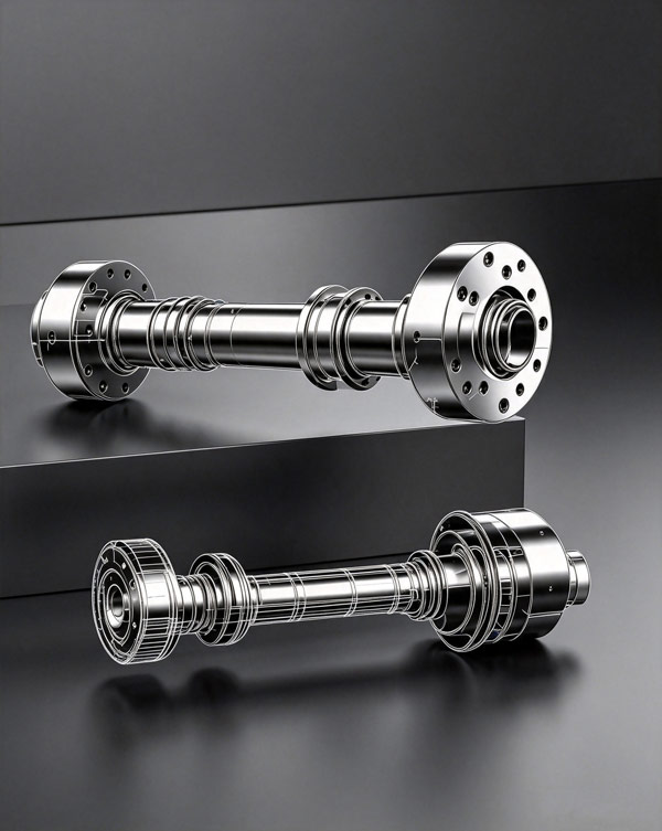
SWP type
cross-shaft universal coupling
SWP type cross-shaft universal coupling
Rated torque16 ~ 1600 kN·m
Swing diameter160 ~ 620 mm
View Details →
Universal Coupling
VF800 type
Material roll universal coupling
VF800 type Material roll universal coupling
Rated torque500 ~ 3000 kN·m
Swing diameter450 ~ 800 mm
View Details →
Universal Coupling